• About Dreisilker
  • Career Opportunities
  • Our Blog
  • Contact Us
  • Request a Quote
Call Dreisilker @ 630-469-7510
Dreisilker Electric Motors
  • Shop Online
  • Branch Locations
    • Illinois
      • Alsip
      • Chicago
      • Crystal Lake
      • Elk Grove Village
      • Glen Ellyn
    • Georgia
      • Marietta
    • Texas
      • Carrollton
  • Repair Services
    • Repair by Type
      • AC Motors
      • Blower Motors
      • Centrifugal Blower Motor Repair
      • Chiller Motor Repair
      • Compressor Motors
      • DC Motors
      • Foreign Motors
      • Gas Booster Repair
      • Gearboxes
      • Gear Motor Repair
      • Generators
      • Printing Press Motor Repair
      • Pumps
      • Servo Motors
      • UL Explosion Proof Motors
      • Vacuum Pumps
      • Wind Turbines
    • Repair Services
      • MotorSafe Repair Process
      • Advanced Varnishing
      • Commutator Repair
      • Machining Services
      • Rewinding Services
        • Armature Repair
        • Armature Rewinding
    • Repair by Industry
      • Heat Treating
      • Crane & Hoist
      • Manufacturing
      • Machine Tool
      • Printing
      • Plastics
      • Steel Mill
  • Field Services
    • Field Services
      • Dynamic Balancing
      • Electronics Repair
      • Infrared Inspection
      • Laser Shaft Alignment
      • Motor and Electronics Troubleshooting
      • Electric Motor Diagnostic Tests
      • Variable Frequency Drive Support
      • Vibration Analysis
    • Engineering Services
      • Electric Motor Contract Manufacturing
      • Complete Machine Shop
      • Balloon and Solid Shaft Repair
  • Motor and Drive Sales
    • All Brands
      • Century Electric Motors
      • CoolBLUE Inductive Absorbers
      • Fasco
      • Genteq
      • Lau
      • Leeson
      • Marathon Electric
      • Optibelt
      • Packard Electric Motors
      • Siemens
      • Yaskawa VFD
      • Teco Westinghouse

Understanding Motor Controls: Starters, Contactors, Overloads, and Disconnects

January 31, 2025/in Electric Motor Protection, Motor Starters, Overload Relays /by Lynn Dreisilker

Starters:

Motor starters control the starting and stopping of electric motors while offering built-in protection features.

Importance of Starters:

  • Soft Start Options: Some starters reduce inrush current, preventing electrical and mechanical damage.
  • Remote & Automated Control: Allows for safer and more convenient motor operation.
  • Integrated Protection: Most starters include overload protection to prevent overheating and excessive current draw.

Types of Starters:

  • Combination Starters: Include a contactor, overload relay, and disconnect switch, simplifying installation and ensuring NEC compliance.
  • Non-Combination Starters: Only contain a contactor and overload relay, requiring an external disconnect switch or breaker.

Example Application: Combination starters are commonly used in industrial HVAC systems, where integrated safety and compliance are required.

siemens starter

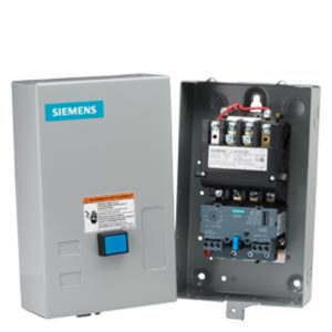
Siemens 14CUB32BA NEMA Size 0 NEMA 1 Enclosure Motor Starter

Contactors

Contactors are electromechanical switches that control power flow to motors, lighting, and industrial equipment.

Importance of Contactors:

  • Handles High Currents: Designed to switch large electrical loads efficiently.
  • Remote Operation: Enables control from a panel or automation system, improving safety and efficiency.
  • Fail-Safe Designs: Many contactors have safety features, such as arc suppression and interlocking mechanisms, to prevent unintended activation.

Types of Contactors:

  • 3-Pole Contactors: Standard for three-phase motors, used in most industrial applications.
  • 4-Pole Contactors: Include an extra pole to switch the neutral wire, useful in backup power and generator transfer systems.
  • 2-Pole Contactors: Used for single-phase motors, such as in HVAC compressor control.
  • Reversing Contactors: Allow a motor to change direction by swapping phase connections.
  • Vacuum Contactors: Used in high-voltage applications, offering superior arc suppression.
  • DC Contactors: Designed for battery-powered equipment, such as electric vehicles and renewable energy systems.

Example: A 4-pole contactor is commonly used in standby power systems, ensuring that both phase and neutral are disconnected when switching between power sources.

Packard 4 Pole Contactor

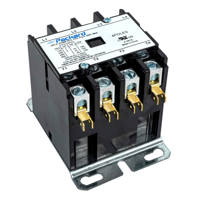
Packard C440C 40 Amps 208/240 Coil Voltage 4 Pole Contactor


Overloads

Overload relays protect motors from excessive current by monitoring electrical load conditions and shutting down the circuit when necessary.

Importance of Overloads:

  • Motor Protection: Prevents overheating and potential motor burnout.
  • Adjustable Settings: Allows customization based on motor size and operating conditions.
  • Safety Compliance: Ensures adherence to NFPA 70 (NEC) and IEC motor protection standards.

Types of Overload Protection:

  • Thermal Overload Relays: Use bimetallic strips to detect excessive heat buildup.
  • Electronic Overload Relays: Provide digital monitoring for precise protection.
  • Magnetic Overload Relays: React to sudden high-current spikes, often integrated with circuit breakers.

Example: In a pump control system, an electronic overload relay prevents damage if the pump gets blocked and starts drawing excessive current.


overload relay

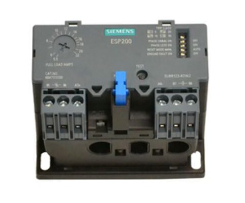
Siemens 48ATC3S00 ESP200 Solid State Overload Relay


Disconnects

A disconnect switch provides a manual way to isolate electrical circuits for maintenance or safety compliance.

Importance of Disconnects:

  • Ensures Safe Maintenance: Prevents accidental re-energization of equipment.
  • Code Compliance: Required by OSHA and NEC regulations for industrial electrical systems.
  • Reliable Isolation: Helps prevent electrical hazards during repairs.

Types of Disconnect Switches:

  • Fused Disconnects: Provide both isolation and overcurrent protection.
  • Non-Fused Disconnects: Used where a separate circuit breaker or fuse provides protection.
  • Enclosed Disconnects: Designed for harsh environments with NEMA-rated enclosures.

Example: A disconnect switch is required in manufacturing plants to isolate conveyor motors for maintenance, preventing accidental restarts.


How These Components Work Together in a System

These four components form the foundation of an industrial motor control system. Here’s how they work together:

  1. Starting the Motor: The operator activates the starter, energizing the contactor, which allows power to flow to the motor.
  2. Monitoring and Protecting the Motor: The overload relay continuously monitors current. If excessive current is detected, the overload relay trips the circuit, stopping the motor before damage occurs.
  3. Isolating Power for Maintenance: Before maintenance, the disconnect switch is used to completely cut power to the motor and control circuit. This ensures safe servicing and compliance with electrical safety regulations.

Conclusion

Understanding the role of starters, contactors, overloads, and disconnects is essential for industrial operators, electricians, and engineers. By selecting and integrating these components correctly, facilities can ensure:

  • Safe operation of motors and electrical systems.
  • Reduced downtime through proper overload protection.
  • Compliance with standards.

By implementing the right motor control solutions, businesses can enhance efficiency, extend equipment life, and minimize operational risks.

How to Increase the Lifetime of a Motor from Two Weeks to Over a Year: Contaminated Environments

May 8, 2020/0 Comments/in Electric Motor Protection, Electric Motors /by Lynn Dreisilker

For over 65 years, Dreisilker has been driven to improve our customers’ reliability and increase uptime through problem solving. A common problem we have found for customers is contamination of the motors, leading to premature failure. A unique customer success story relating to failure from contamination involved motors that were failing every 2 weeks. Through talking with the customer and examining their operations, we were able to help them improve the motors’ reliability.

Customer Success Story:

Our customer talked with us about a series of motors that were failing every 2 weeks or less. The motors power large rollers that have water being sprayed over large steel slabs for cooling purposes. The water was negatively affecting these motors and causing failure every two weeks. While the replacement motors were relatively economical, the cost of downtime and the added cost of the labor to uninstall and reinstall was adding up. Our customer asked us if we would be able to come up with a solution to help these motors last 4 to 6 months versus 2 weeks.

Ultra Seal Application

Ultra Seal Application

Our engineering team worked with our customers’ maintenance crew to figure out the best solution for this issue. After reviewing the motor and its application, we determined that it would be best to utilize our Ultra Seal winding technique to fully insulate the motor’s winding and protect it from contamination. The Ultra Seal Winding technique involves us fully impregnating and sealing the coils with a high molecular weight thermoset polymer resin. Below shows a winding before and after the Ultra Seal Winding process.

Left: Ultra Sealed windings. Right: Normal windings.

Crosscut of Ultra Sealed windings.

The customer agreed to try out an Ultra Sealed motor to see how long it would last. The process involved us purchasing a brand new motor, stripping the motor of its windings, winding a new core, and then using our Ultra Seal process. If you are wondering why we would need to strip a brand new motor of its windings, it is because the Ultra Sealed windings do not require standard motor varnish (see our blog on different types of varnishing methods) and it actually acts as the insulator for the windings.

New motor to be Ultra Sealed.

New motor after being Ultra Sealed.

We delivered the new, Ultra Sealed motor to our customer and they put it into production. Two weeks passed by with the motor still running and it exceeded their desired 4-6 month target. The customer recognized the reliability of the new motor and ordered more for the operations and they have been running for over a year.

Some common industrial applications for Ultra Sealed motors include:

• Machine tool CNCs – Servo and Spindle Motors
• Steel Mills: Continuously wet and hot environments that demand reliable 24/7 uptime
• Poultry Processing Facilities
• Irrigation Operations.
• Pulp & Paper Mills
• Mining Operations
• Plastics Injection Molders.
• Petroleum Drilling Operations
• Food Processing
• Foundry Operations

While heat dissipation was not a clear problem with the customer success story above, it is still important for other applications. In addition to protecting the motors from contamination, the Ultra Seal Winding allows for efficient cooling of the motors. The resin used within the process is approximately 40 times more efficient at heat transfer than air. This is useful especially for motors found in extreme temperatures.

If you have motors operating in harsh environments and they are failing prematurely, you may want to consider the Ultra Seal method. Reach out to us today if you have questions regarding the process or would like a quote.

Aegis Shaft Grounding Rings Protect your Motors and Bearings

June 6, 2018/0 Comments/in Aegis Shaft Grounding Rings, CoolBlue, Electric Motor Protection, Variable Frequency Drives /by Lynn Dreisilker

Aegis Shaft Grounding Rings protects bearings and electric motors from damaging shaft voltages caused by variable frequency drives (VFDs). The voltages emitted by VFDs find their way to ground typically through the motor’s bearing. Some signs of these damaging currents include pitting, frosting, fluting and loss of bearing lubrication. Installing Aegis Shaft Grounding Rings to your motors can prevent bearing and motor failure caused by the shaft voltages.

The Aegis Shaft Grounding Rings work by diverting the damaging voltages away from the bearings by sending it to ground through the motor frame. The rings are made of conductive microfibers that encircle the motor shaft and is installed on the drive end of the motor. For motors 100HP and higher, it is recommended to use an insulated bearing on the non-drive end with the Aegis Ring installed on the drive end.


 Aegis Shaft Grounding Rings Kit
Aegis Shaft Grounding Ring Kit.
 Aegis Shaft Grounding Rings Diagram 2
Conductive Microfibers.
 Aegis Shaft Grounding Rings Diagram
Diagram of an Aegis Shaft Grounding Ring.


Even though a motor may be rated inverter duty, you need to keep in mind that this does not mean that it comes with grounding rings preinstalled. If you need an inverter duty motor with grounding rings pre-installed, you will need to select the option for grounding rings. Most motors now have the option to come with grounding rings preinstalled. If you already have a motor in the field that needs protection, you can order an Aegis Shaft Grounding kit and install it on your motor.

There are different types of Aegis Rings that allow for installation on many applications. They are available in solid and split-ring designs, configured for NEMA and IEC motors, and include four mounting bracket styles and hardware. The different types of Aegis Rings can be found in our online store. If you need assistance finding the proper Aegis Rings for your application, we are able to help you source the rings.

Whenever you have a motor with grounding rings installed, you should add visually examining the Aegis Rings to your preventative maintenance checklist. Like most parts of a motor operation, grounding rings can be negatively affected by contamination. While checking your motors, inspect the rings for any sign of contamination that can cause ineffectivity of the ring. Aegis now offers a 2 year warranty against fluted bearings when you register your rings with Aegis.

Although the Aegis Shaft Ground Rings are a trustworthy solution to protect your motors, it is not the only solution to prevent damaging currents emitted by VFDs. Another solution that we highly recommend you utilize in conjunction with the Aegis Rings is CoolBlue Inductive Absorbers. CoolBlue are common mode chokes that are installed by placing the CoolBlue rings around the motor’s lead wires. To learn more about CoolBlue and its benefits, read “How CoolBlue Protects Your Motors and Bearings.”

If you are utilizing VFDs in your operations, you should consider protecting your bearings from damaging currents through the use of Aegis Shaft Grounding Rings and CoolBlue.

How CoolBlue Protects Your Motors and Bearings

April 17, 2018/0 Comments/in CoolBlue, Electric Motor Protection, Variable Frequency Drives /by Lynn Dreisilker

CoolBlue Inductive Absorbers protect motors and bearings from high frequency currents caused by Variable Frequency Drives. Without CoolBlue, damaging currents emitted by variable frequency drives can lead to bearing damage and ultimately electric motor failure. Some types of bearing damage include pitting, fluting, frosting of bearings, lubrication break down and overall destruction of the bearing.

CoolBlue are inductive absorber rings that are installed on all three power phase lead wires between the variable frequency drive and the electric motor. Once installed, CoolBlue acts as a common mode choke that reduces transient voltages, stray capacitive currents and common mode currents before they reach the electric motor.

CoolBlue Application Diagram web

Installing CoolBlue in your variable frequency drive applications can prevent production downtime, additional maintenance, costly motor repair, and expensive bearing replacement. In addition to the benefits of protecting your bearings and motors, CoolBlue is easy to install, lasts the lifetime of your motor and is maintenance free.

Common applications for CoolBlue include:

  • OEM Manufacturers of HVAC Equipment
  • Paper/Bottling/Food/Chemical Manufacturing
  • Washdown Applications
  • Hospital, Office and Commercial Buildings
  • Automobile and Related Product Manufacturing
  • All Pump and Fan related applications
  • Wind, Solar and other renewable energy applications
  • All Variable Frequency Drive Applications

How to Select the Correct CoolBLUE products:

See our full blog on our CoolBLUE selection guide here: How to Select the Correct CoolBLUE for your Application

For more specialized motor applications that require higher reliability, Nanoperm Line Absorbers (NaLa) are recommended in addition to CoolBlue Inductive Absorbers. NaLa further reduces the variable frequency drive noise and peak values of current. Unlike CoolBlue, NaLa is installed on each of the power phase wires, not over all three power phases. NaLa is to be used in conjunction with CoolBlue to further increase the reliability and uptime of your motor system.

The CoolBlue and NaLa products are sized by HP and total cable length from the VFD to motor.  If there are two cables on each output leg then the distance needs to be multiplied by 2 or so on for each added cable per phase.  There are 4 popular sizes that are stocked that cover from 1/4HP to 400HP. When lead lengths are longer then 150ft, 300ft, 450ft, and 900ft, then more cores are added to the system. For more information on how to properly install CoolBlue, see this installation guide.

One major advantage of installing CoolBlue and NaLa is the reduced installation time needed over other options.  Also, there is no need for an insulated bearing on motors with over 100 HP. CoolBlue and NaLa are readily available at Dreisilker Electric Motors, Inc.

In addition to the usage of CoolBlue in VFD applications, you can also protect your motors with Aegis Shaft Grounding Rings. The Aegis Rings work by diverting the damaging voltages away from the bearings by sending it to ground through the motor frame. The rings are made of conductive microfibers that encircle the motor shaft and is installed on the drive end of the motor. To learn more about the Aegis rings, read our blog Aegis Shaft Grounding Rings Protect your Motors and Bearings.


Request a Quote for CoolBlue

Electric Motor Protection: Basics of Overload Relays

March 14, 2018/0 Comments/in Electric Motor Protection, Motor Starters, Overload Relays /by Lynn Dreisilker

Motors can be damaged by excess heat caused by current flow when there are overload conditions. Some examples include a locked shaft, too many systems on a circuit, the power supply single phasing on a three phase circuit. Installing overload relays in your applications can protect your motors.

Why are Overload Relays needed?

When a motor starts, it typically requires 6 times the full-load current rating. After the motor ramps up to operating speed, the current drops off. Motors are designed to handle this overload condition only for a short period of time. If a motor maintains this overload condition, the motor will overheat and potentially become damaged.

While fuses and circuit breakers can protect your system from short circuits, ground faults, or an overload, they are not the proper protection device for motors. As noted above, motors pull significantly more amps at startup than their full-load current rating. Any fuse used with a motor would need to be rated to handle this higher startup amp draw, therefore it would fail to protect the motor from overload conditions beyond normal startup. Overload relays are designed to allow temporary overloads for a specific period during startup. If the overload persists, the overload relay will trip and break the circuit to protect your motor. Overload relays can be easily reset after the overload is corrected.

Overload Relay Trip Classes

Overload relays have a trip class rating for different applications. The most common trip classes are Class 10, Class 20 and Class 30. The number in a trip class is simply the total number of seconds that the motor is allowed to overload before the circuit trips. For example, if you have an overload relay with a Class 10 rating, your system will allow an overload condition for 10 seconds before the overload relay trips to protect your motor.

Types of Overload Relays

A few different types of overload relays include Bimetal Overloads, Ambient-Compensated Overload Relay, and Electronic Overload Relays.

  • Bimetal Overloads use a bimetal strip that acts as a trip lever. When there is an overload condition, the bimetal strip becomes heated and will bend to close and trip the circuit.
  • Ambient Compensated Overload Relays are similar to Bimetal Overloads. The main difference is that the Ambient Compensated Relays allow for there to be an ambient temperature, such as the temperature of the surrounding environment. These relays can prevent false tripping by allowing the ambient temperature to be higher.
  • Electronic Overload Relays do not have heaters found in Bimetal and Ambient-Compensated Overload Relays. The Electronic Overload Relays also offer phase loss protection by detecting phase losses and disconnecting the motor from the power source. There are many types of Electronic Overload Relays to fit a lot of applications.

Installing overload relays in motor applications will prevent motors from running in overload conditions and can protect your motors from damaging heat. There are many types and settings for overload relays. If you need guidance finding the right overload relay for your application, call us today!


Request a Quote

Post Categories

  • Aegis Shaft Grounding Rings
  • Bearings
  • Belts
  • Brushes
  • Company News
  • Condenser
  • CoolBlue
  • Cooling Season
  • DC Motors
  • Efficiency
  • Electric Motor Protection
  • Electric Motors
  • Fan Blades
  • Field Services
  • Heating Season
  • Infrared Inspection
  • Motor Repair
  • Motor Starters
  • News
  • Overload Relays
  • Predictive Maintenance
  • Reliability Services
  • Servo Motors
  • Uncategorized
  • Variable Frequency Drives

Dreisilker Information

  • About Dreisilker
  • Career Opportunities
  • Our Blog
  • Contact Us
  • Request a Quote

Quick Links

  • Branch Locations
  • Repair Services
  • Reliability and Field Services

STAY UP TO DATE –

Sign up for our newsletter:


Scroll to top