How to: Laser Shaft Alignment
Why Shaft Alignment Matters
Alignment in your machines is vital to the reliability of your operations. When two machines are misaligned, severe failure can occur causing unplanned downtime and loss of revenue. Some negative consequences are seal failure, bearing failure, energy loss from inefficiencies, increased vibration, and excessive heat.
Common Shaft Alignment Issues
For normal operation, both of the machines’ shafts need to be collinear, meaning that they are in the same line. When equipment is misaligned, several different conditions may occur:
-
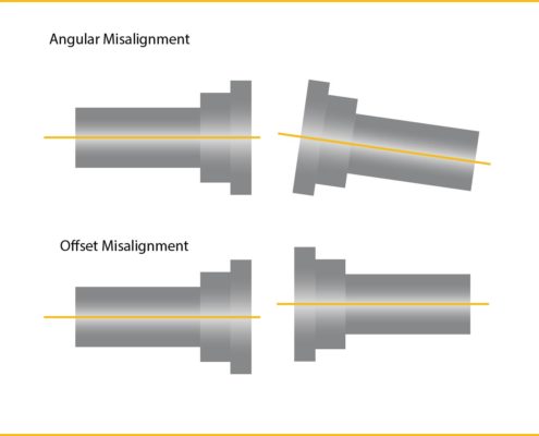
Angular Misalignment – Shafts meet at an angle rather than being parallel, causing uneven load distribution.
-
Parallel (Offset) Misalignment – Shafts are parallel but offset either horizontally or vertically, increasing vibration.
-
Combined Misalignment – A mix of angular and parallel misalignment, often the most harmful.
-
Soft Foot – When one motor foot does not sit flat, the frame distorts as bolts are tightened, leading to shifting alignment.
-
Thermal Growth – As equipment heats up, alignment shifts from its cold condition, making “hot alignment” adjustments necessary.
The Laser Shaft Alignment Process
To check alignment of your machines, we utilize laser technology to accurately test the alignment. Here are the steps we use to align motors and generators to their mates:
Prealignment
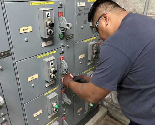
- Safety Check: We follow Lock Out Tag Out (LOTO) procedures to ensure no energy is present or available in the systems we are working on. Safety guards are then removed for access to adjustment points.
- Mounting Check: All mounting surfaces and conditions are checked prior to installing the motor. Both the feet and the mounting base should be clear of any rust, paint or dirt.
- Soft Foot Check: We use the Pruftechnik ROTALIGN Ultra iS to check the motor for soft foot (distortion of the equipment frame). ). If your motor or generator has soft foot, a false alignment of the bearings internally can occur cocking one or both bearings in the housing. This means that one foot could be tightened down and distort the bearing housing too much putting tension on the bearings. IEEE 1068‐2015 specifies a coplanar tolerance of 0.005 inches (0.127 mm) of the motor feet on a fully assembled motor. Click here to learn how a motor frame can warp via burnout oven stripping.
Alignment Steps
- Fasten Brackets: Brackets are fastened to the driven shaft and the driving shafts.
- Mount Laser: The laser is mounted to the stationary end and the receiver to the end that will be in motion.
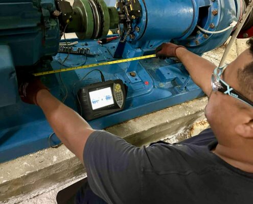
- Conduct Alignment Check: Using our Pruftechnik equipment, we select what types of equipment we are analyzing (ie. Motor + pump, motor + air compressor, and etc), input the dimensions of the equipment, and the points where the laser and receiver are located. We then manually and simultaneously turn both shafts 360 degrees by hand to conduct a test. The equipment takes a reading at every degree and calculates the level of movement as it goes around. The parameters are within thousandths of an inch. After the full 360 degree rotation, we can analyze the data on our equipment. The equipment will inform us to correct the machine positions.
After the first adjustments, we check the alignment again, repeating the same alignment check until the machines are aligned within proper tolerances.
Sometimes a “hot alignment check” is necessary. Machines can grow or shrink during operation causing misalignment. We run the equipment for a period of time to see if there is any thermal growth or shrinkage. It is necessary to align the motor or generator to its proper working conditions.
During the alignment process of a non reconditioned or new motor/generator, our technicians can find other problems. For example, if alignment is off from 5 to 6 thousandths of an inch after each check, this is a sign that the bearing housings could be loose. Our technicians will recommend if bearings need to be replaced, machining is needed, or other improvements to extend the service life of your machines. In some instances, we can also make recommendations on the remaining service life, based on the condition of the motor/generator or load.
Benefits of Laser Shaft Alignment
By investing in proper alignment, you gain immediate and long-term benefits:
-
Reduced vibration and noise
-
Lower wear on bearings, seals, and couplings
-
Improved energy efficiency
-
Extended equipment life
-
Fewer breakdowns and unplanned outages
Overall, alignment is a crucial step to maximizing the amount of profit you can get out of a motor, generators, or loads service lifetime. Improper alignment will cost you and your operation money!


