The Goal
“To evaluate physical changes, core loss, hotspots and visual conditions of a 100 HP and a 200 HP AC 3 Phase induction motor after they have been stripped using the Burnout Oven Incineration Method.”
Preparation and Measurement Criteria
Burnout Oven Preparation
- Calibrate burnout oven prior to use
- Place stator frames on feet in burnout oven and with centers perpendicular to each other
- Set burnout oven to 750 F for inorganic laminations
- Test the fire suppression prior to oven starting
- Set oven operation cycle for 8 hours
Measurements
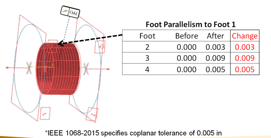
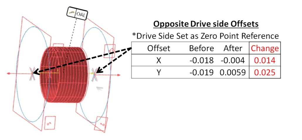
- Measure Flange, Feet, and Lamination Bore using a calibrated coordinate measuring arm
- Measure core loss using a calibrated core loss tester
- Measure hotspot temperatures using a calibrated infrared camera
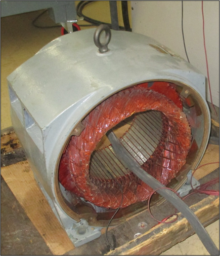
Before the Study 100 HP
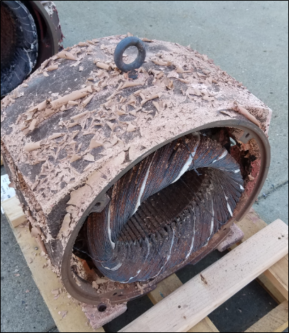
After the Study 100 HP
Core Loss Results

Core Loss Results

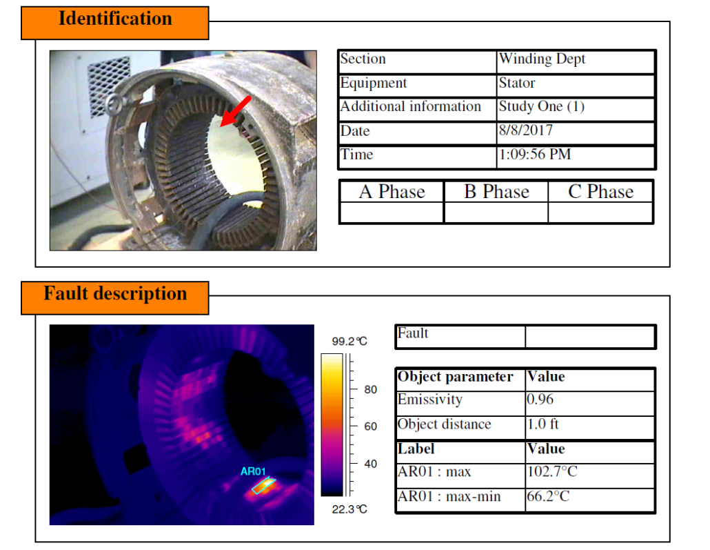
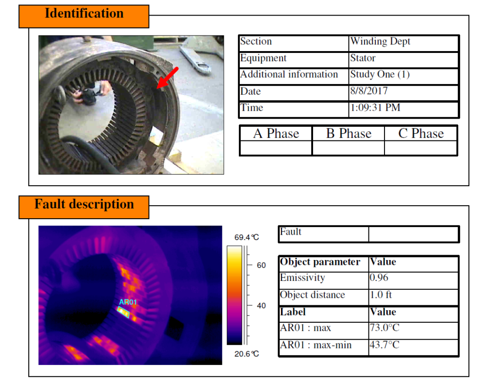
100 HP Infrared Inspection
The images below are just a sample of the infrared inspection we conducted on the 100 HP stator. As you can see in the infrared pictures, there are multiple hot spots found in the stator’s core. Hot spots lead to efficiency and reliability loss in your motor’s operation.
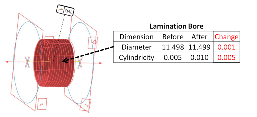
100 HP Physical Measurements
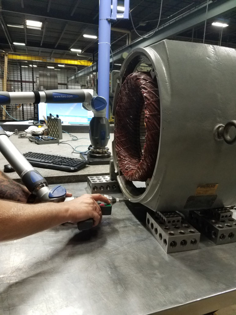
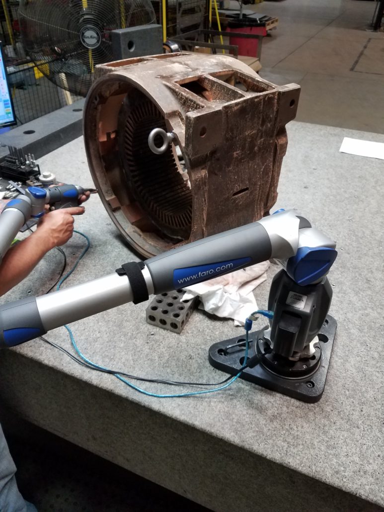
We used a calibrated coordinate measuring arm to measure the motor’s flange, feet and lamination bore to detect any physical changes of the motor after the Burnout Oven Incineration method was used.
Dangers of Low Quality Rewind Process
- Failure from Loose Windings/Vibration
- Susceptibility to Contamination
- Poor Heat Transfer
- Imbalanced Current and Temperature
- Insulation Failure
- Phase Imbalance
- Metallurgical Change in Electrical Steel
- Increasing Operating Costs
- Core Loss
- Efficiency Loss
- Power Factor Decrease
- Physical Deformation of Motor Components
- Air Gap Change
- Bearing Misalignment
- Warping of Motor Frame
- Soft-Foot
