Basics of Variable Frequency Drives
Variable Frequency Drives (VFDs) are used to adjust the speed of motors. There are many different names for VFDs including adjustable speed drive, adjustable frequency drive, AC drive, microdrive, and inverter drive. VFDs adjust the speed of motors by changing the frequency being transferred to the motor. For example, when the VFD is receiving power at 60 hz, it can change the frequency to 20 hz, resulting in a slower rotation of the motor.
The Different Parts of a Variable Frequency Drive:
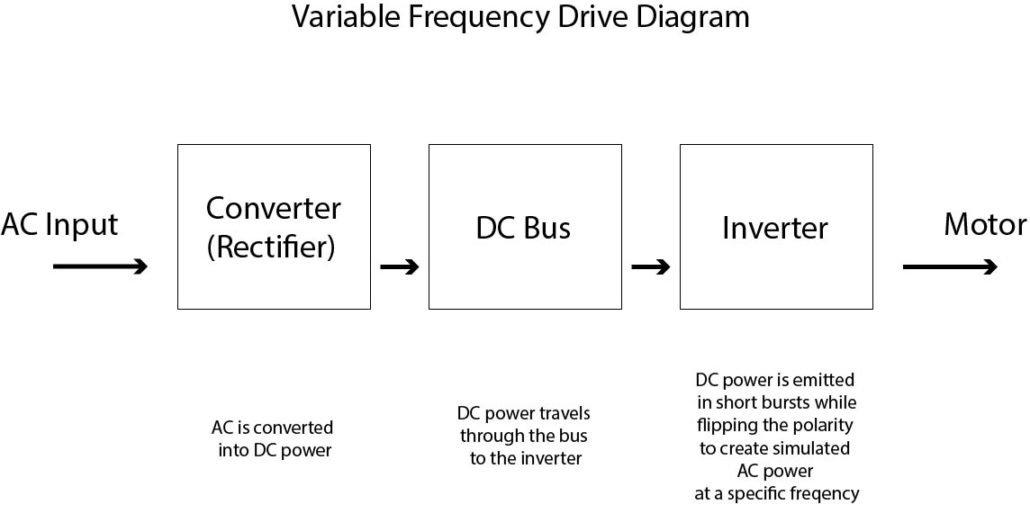
The three parts of a VFD that allow the drives to change frequency are the converter, dc bus, and inverter sections.
- Converter: AC power enters the VFD’s converter which converts the power from AC to DC power.
- DC Bus: After it is converted, the power travels through the DC Bus.
- Inverter: The power then enters the inverter section which is made up of small circuit board components called insulated gate bipolar transistors (IGBT). The IGBT act as triggers to take the dc power to spit out the dc power in short bursts, then flips the polarity. The IGBT continues spitting out the power in short bursts and flipping the polarity.
The outcome is Pulse Width Modulation (PWM) which is a simulated AC power at a specific frequency.

Some benefits of using VFDs include:
- Mechanical stress and belt wear on equipment is far less when using a drive versus across the line starting of a motor.
- Motors running on drives are protected from incoming power surging and single phasing.
- Reducing the speed of a motor by 20% will reduce the power consumption of a motor by 50%, calculated using the affinity law.
- High efficiency at low speed
- Speed Variation
Selecting and Installing the Right VFD
Choosing the correct VFD for your application is critical to getting optimal performance and long-term reliability. Factors like motor size, load type (variable or constant torque), environmental conditions, and control requirements all impact drive selection. Proper installation is equally important—ensuring the drive is wired correctly, configured for your motor, and protected from external factors like heat, dust, and vibration. At Dreisilker, we help customers every step of the way, from selecting the right drive to professional installation and troubleshooting support. Whether you’re managing the install yourself or need a full turnkey solution, our team is here to ensure your system runs efficiently and reliably.

What are the Different Torque Requirements?
There are two types of torque requirements found in VFD applications, including variable torque load and constant torque load. Variable torque loads are typically found in applications like fans, blowers, spinning compressors and spinning pumps which move easy loads such as air or (clean) liquid. The application requires more torque as you are moving more of the air or fluid. As the motor or pump speeds up, the amount of force required to move the load increases. The increase in the need of force is why they are considered variable torque loads.
Conversely, Constant Torque loads are found in the applications that require the same amount of torque to move the loads at slower and faster speeds. Common constant torque loads are found in conveyors, elevators, shredders and extruders.
Both types of torque loads need to be able to provide the application with their full load amps (fla) which is 100%. Variable torque loads can provide an application with low overload capability of 110% fla for instances when the load changes or if it encounters extra loads momentarily. Constant torque loads are designed to allow 150% fla which is considered high overload capability. The high and low overload capabilities allow for the application to handle the temporary overload without the motor shutting down.
Are there any downsides to VFDs?
Although VFDs allow for improved motor efficiencies, they also present a problem for motor bearing life. The VFDs can emit damaging currents that go to ground through a motor’s bearing. Eventually, this can lead to pitting, fluting, frosting of bearings, lubrication break down and overall destruction of the bearing. The harmful currents can be stopped by installing CoolBlue Inductive Absorbers and Aegis Grounding rings. To learn about these products, you can read our blogs CoolBlue Inductive Absorbers and Aegis Shaft Grounding Rings.

Since I’ve been involved with the fan & blower business for many years I’m pretty much aware of the information shown in this article. However, the information shown could prove valuable to new people in the industry and is an excellent primer. Good Job!